 400G
400G 200G
200G 100G
100G 40G
40G 25G
25G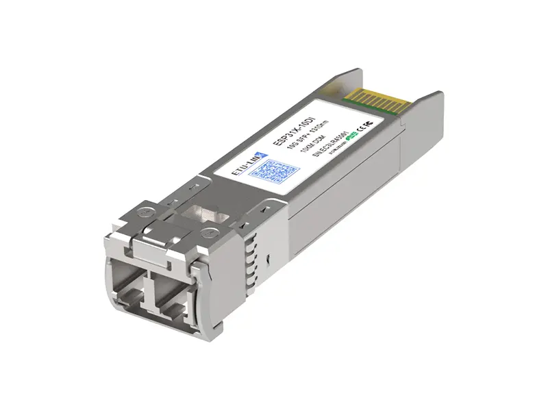 10G
10G 1G
1G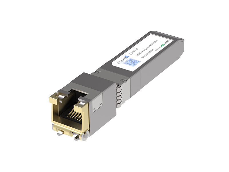 COPPER-T
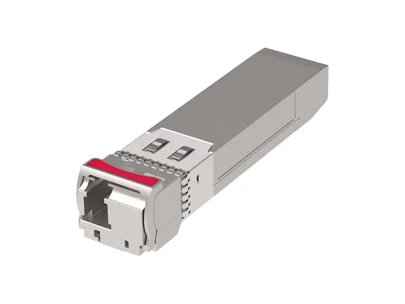 Other
Other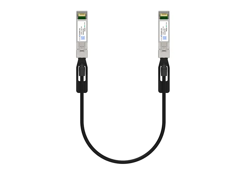 10G SFP+ DAC
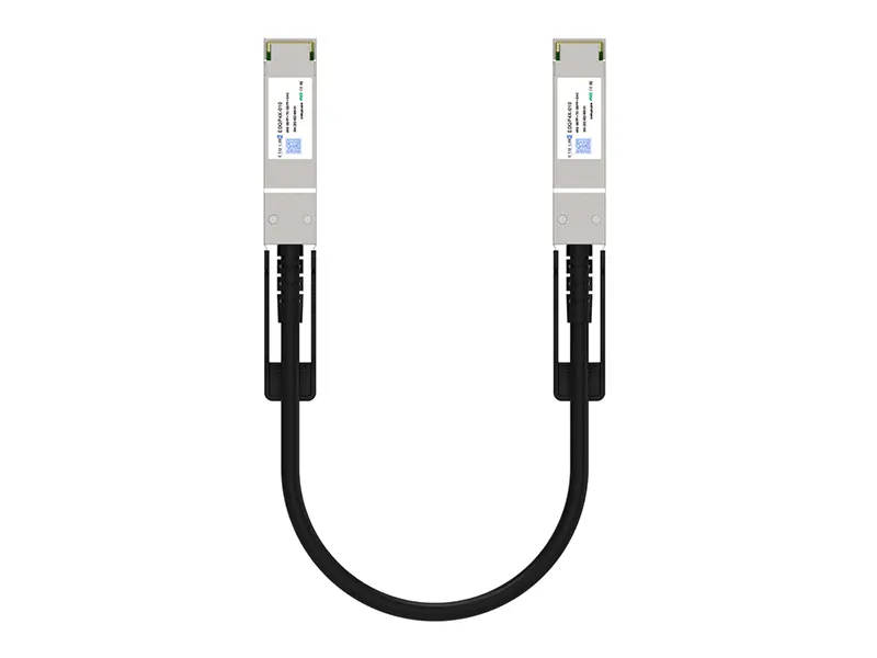 40G QSFP+ DAC
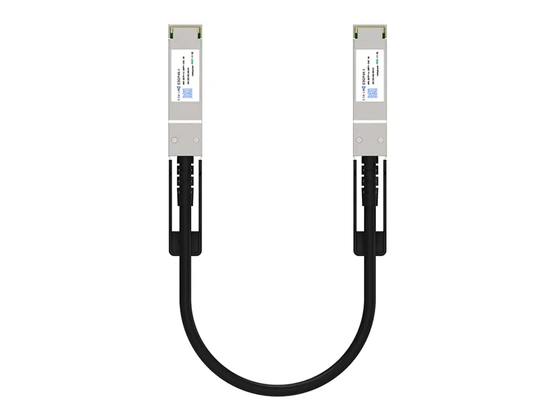 56G QSFP+ DAC
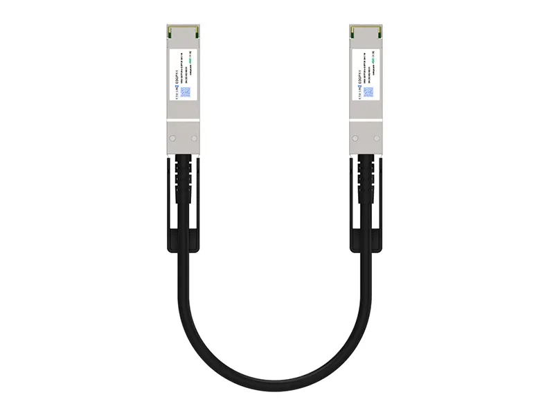 100G QSFP28 DAC
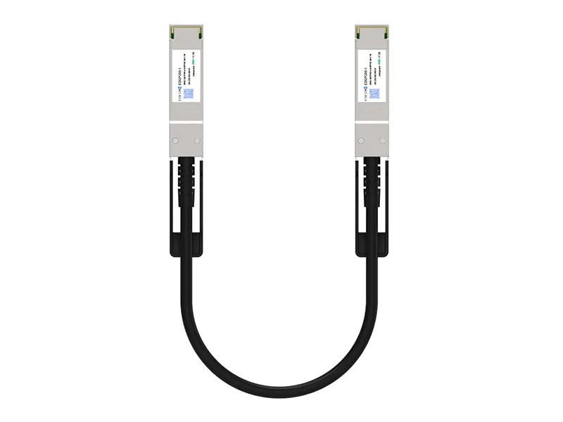 200G QSFP56 DD DAC
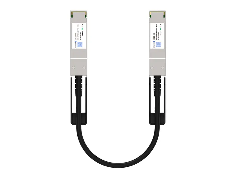 400G QSFP DD DAC
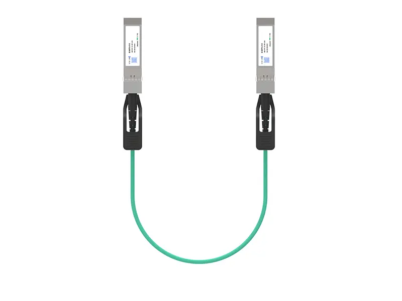 10G SFP+ AOC
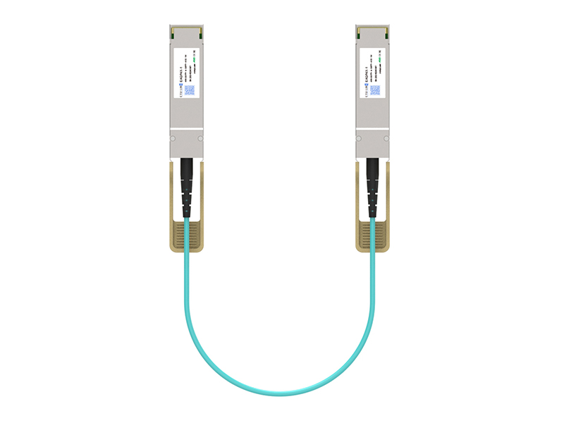 40G QSFP+ AOC
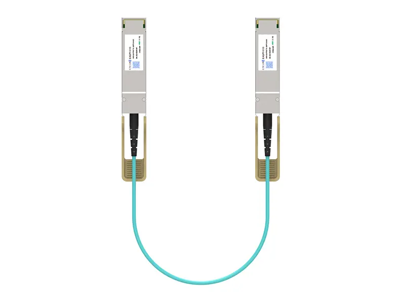 100G QSFP28 AOC
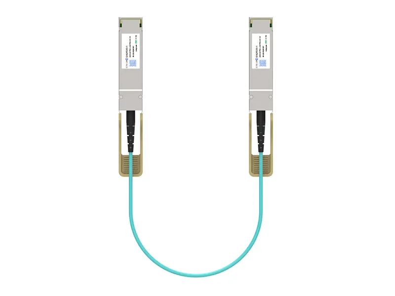 200G QSFP56 AOC
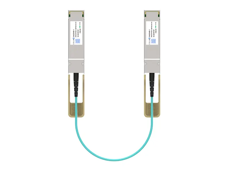 400G QSFP-DD AOC
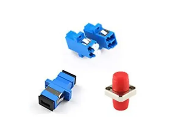 Adapter Details
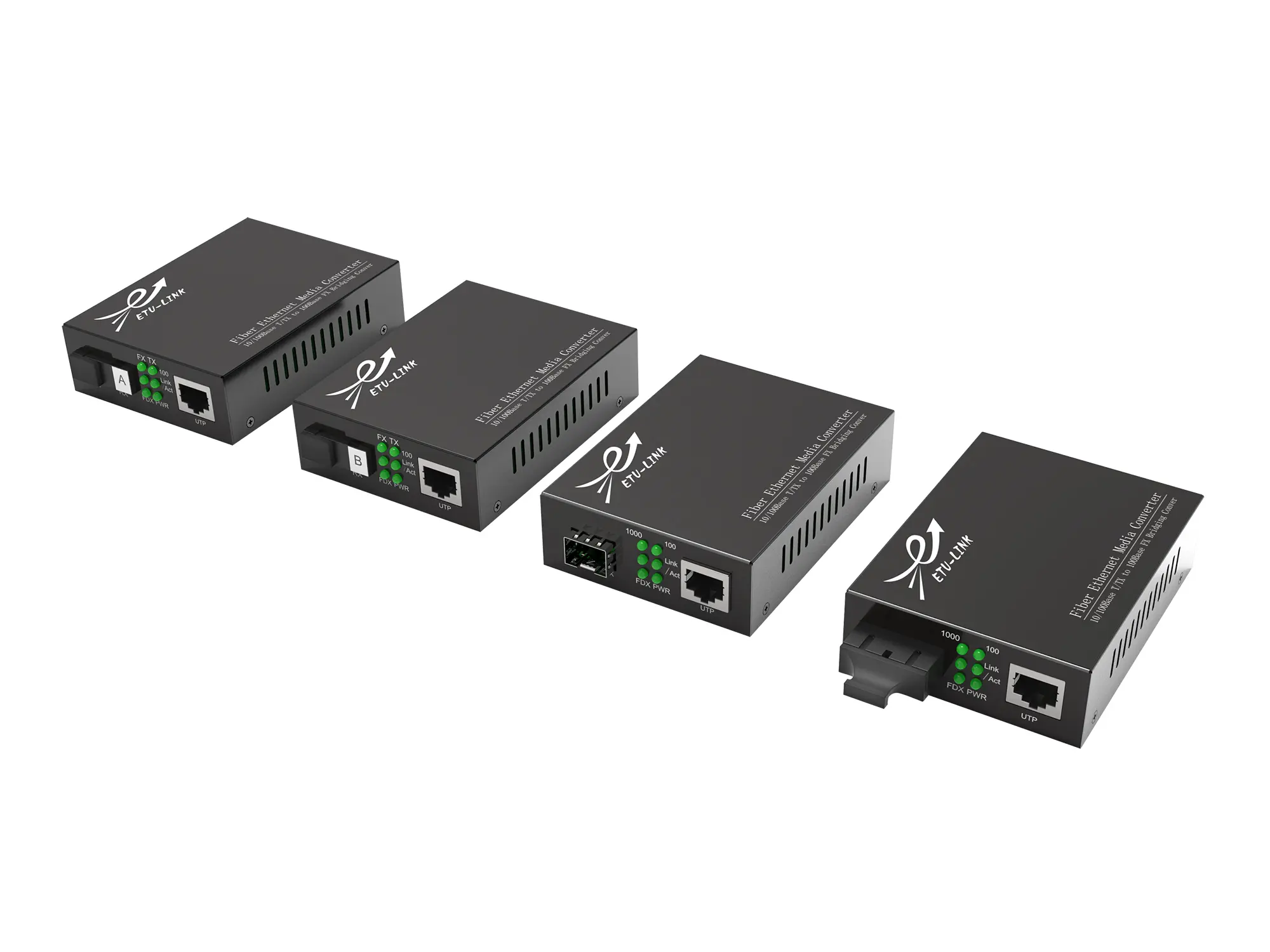 Media Converter
Leave Your Message
Choosing the right SFP+ 10G Transceiver is not simply a matter of matching speed. The correct module must fit the switch, cable path, distance, wavelength, and operating environment. A 10GBASE-SR transceiver suits short multimode-fiber links, often inside a data center. A 10GBASE-LR model supports longer single-mode-fiber connections, but it usually costs more. Direct-attach copper can be cheaper for short rack connections.
John D’Ambrosia, a recognized Ethernet standards expert, has said, “Interoperability is the key to Ethernet’s success.” That principle matters when selecting an SFP+ 10G Transceiver. Check the equipment manufacturer’s compatibility list before purchasing. Verify the connector type, fiber mode, transmission distance, temperature range, and digital optical monitoring support. DOM can reveal live readings, including temperature, voltage, and optical power. These details help technicians identify weak links before a network outage occurs.
Real installation work also exposes uncomfortable limitations. A module may function during testing but fail after heat builds inside a crowded rack. A low-cost transceiver may appear attractive, yet its coding or vendor lock can create compatibility problems. Product labels are not always enough. Compare test reports, warranty terms, return policies, and supplier reputation. Use an optical power meter when possible. Still, no checklist is perfect. Firmware changes, aging fiber, and poor cleaning can alter results. Careful selection reduces risk, but reliable performance requires testing, documentation, and periodic review.
An SFP+ 10G transceiver is a small, replaceable module that connects network equipment to high-speed fiber or copper cabling. It supports data rates up to 10 gigabits per second, depending on the device and connection standard. The module sits inside an SFP+ port and exchanges electrical signals with the switch or server.
On a fiber link, the transmitter converts electrical data into pulses of light. The receiver changes those light pulses back into electrical signals. A duplex connection usually uses separate paths for sending and receiving. The transmission distance depends on the fiber type, wavelength, and optical power. In real installations, dust, sharp cable bends, and mismatched wavelengths often cause trouble. The specification sheet is helpful, but it is not always enough.
Tips: Check the host port, data rate, connector type, fiber mode, wavelength, and supported distance before buying. Confirm whether digital monitoring is available for temperature and optical power. Test the module with the actual cable when possible. This catches problems early. A common mistake is choosing by speed alone. Compatibility can be more complicated than expected. Also, leave room for airflow around densely installed modules, because heat can reduce link stability. One detail is easy to overlook: the transceiver and cable must support the same transmission method. Rechecking the full link is worth the extra minute.
| Selection Dimension | Typical Option | Key Technical Data | When to Choose It |
|---|---|---|---|
| Data Rate | 10 Gb/s Ethernet | Designed for 10 Gigabit Ethernet; the common line rate is 10.3125 GBd with 64b/66b encoding. | Use it for 10GbE switch, server, storage, or uplink connections. Confirm that the host port supports SFP+ rather than only lower-speed SFP operation. |
| Form Factor | SFP+ | Small form-factor pluggable module with a standard electrical host interface and hot-swappable installation. | Choose SFP+ when port density, replaceability, and compatibility with SFP+ cages are important. Verify the equipment interoperability requirements before purchase. |
| Optical Mode | Multimode fiber (MMF) | Commonly uses an 850 nm VCSEL transmitter and duplex LC connectors. | Best for short-distance data-center and building links where OM3 or OM4 multimode fiber is already installed. |
| 10GBASE-SR Reach | Short reach | 850 nm over multimode fiber; up to 300 m on OM3 and up to 400 m on OM4 under typical IEEE-defined link conditions. | Select SR for economical short-reach connections inside data centers or between nearby network cabinets. |
| 10GBASE-LRM Reach | Long-reach multimode | Typically operates near 1310 nm and supports distances up to 220 m over suitable multimode fiber. | Use LRM when an existing multimode-fiber installation exceeds common SR performance or has older fiber characteristics. |
| Optical Mode | Single-mode fiber (SMF) | Uses a narrow optical mode suitable for longer distances; duplex LC connectors are common. | Choose SMF for campus, metro, carrier, or data-center interconnects where the link exceeds multimode limits. |
| 10GBASE-LR Reach | Long reach | 1310 nm over single-mode fiber; typically supports up to 10 km, subject to link loss and fiber quality. | Select LR for long building-to-building, campus, and metro links that require standard 10GbE interoperability. |
| 10GBASE-ER Reach | Extended reach | 1550 nm over single-mode fiber; typically supports up to 40 km with an appropriate optical link budget. | Use ER for extended metro or wide-area links. Check dispersion, attenuation, connector loss, and the equipment's supported optical specifications. |
| Bidirectional Operation | BiDi / WDM | Transmits and receives over one single-mode fiber using two different wavelengths; requires a matched wavelength pair at opposite ends. | Choose BiDi when only one fiber strand is available. The upstream and downstream modules must be installed as a compatible pair. |
| Copper Alternative | 10GBASE-T SFP+ | Uses a twisted-pair RJ45 connection and generally supports up to 100 m over suitable Category 6A cabling. | Select copper when existing structured cabling and RJ45 connectivity are preferred. Consider higher power consumption and possible thermal limits. |
| Direct-Attach Cable | Passive or active DAC | Fixed twinax cable with SFP+ ends; passive versions are commonly used for short links, often up to about 7 m, while active versions can extend farther depending on the specification. | Use DAC for low-cost, low-latency rack-to-rack or server-to-switch connections when a fixed cable length is acceptable. |
| Host Power Supply | 3.3 V nominal | The module receives a nominal 3.3 V supply from the host equipment; actual power draw varies by optical type and module design. | Check the host port's maximum module power and thermal capacity, especially for copper, extended-reach, or high-temperature deployments. |
| Digital Diagnostics | DDM / DOM | May report temperature, supply voltage, laser bias current, transmit power, and receive power through a digital management interface. | Choose diagnostic monitoring when proactive fault detection and link-budget troubleshooting are required. Confirm host software support. |
| Operating Temperature | Commercial, extended, or industrial | Common module ranges include 0–70 °C commercial, −20–85 °C extended, and −40–85 °C industrial; exact limits depend on the module specification. | Match the temperature grade to the equipment enclosure, airflow, outdoor cabinet, or industrial environment. |
| Compatibility | Host port and coding support | Mechanical fit alone does not guarantee operation. The host may check module identification, supported Ethernet modes, optical parameters, and vendor coding. | Verify the switch or network adapter's approved module list, port speed, firmware behavior, connector type, and required fiber standard before ordering. |