How to Choose the Right Cisco DWDM SFP+ Transceiver
Choosing a Cisco DWDM SFP+ transceiver is a link-design decision, not a simple parts lookup. The module must match the fiber path, channel plan, distance, and equipment at both ends. A mismatch can leave a link dark, unstable, or outside its supported optical budget.
The demand for capacity is substantial. Cisco’s Annual Internet Report, published in 2020, projected global IP traffic would reach 3.3 zettabytes annually by 2021. That figure was a forecast, not a current measurement, but it illustrates why dense wavelength-division multiplexing remains important in high-capacity networks. For a real deployment, check the exact Cisco platform and software support, wavelength, channel spacing, transmission reach, connector type, and receive-power limits. Read the link budget carefully. A few decibels matter.
Optical-networking author David McDysan has written extensively about engineering DWDM systems. The practical takeaway here is an editorial paraphrase, not a verbatim quotation: “Choose the complete optical path, not just the module label.” That distinction is easy to overlook. A transceiver marked for the right distance may still be unsuitable if its wavelength or channel plan differs from the far-end optic. Before ordering, compare both endpoint specifications and confirm whether dispersion, amplification, or intermediate optical equipment affects the path. Then validate compatibility against Cisco’s documentation and measure the installed link. Real fiber routes can be messier than a clean diagram. That deserves a second look. This guide explains how to choose a Cisco DWDM SFP+ transceiver with those practical checks in mind.

Define the Link Requirements for a Cisco DWDM SFP+ Transceiver
Before selecting a DWDM SFP+ transceiver, define the link at both ends. Record the required data rate, fiber type, connector, and actual route length. A map may show 35 kilometers, while patch panels and service loops add several more. Small details matter.
Identify the DWDM channel or wavelength required at each endpoint. Confirm that the two modules use compatible transmit and receive wavelengths, and that the optical plan supports the intended channel spacing. Check whether the link uses one fiber or a pair. Do not assume both ends need identical modules; some designs use matched pairs, while others require different wavelength variants. That assumption is easy to make, and sometimes wrong.
Calculate the optical budget using transmitter output, receiver sensitivity, and estimated losses from fiber, connectors, and splices. Leave practical margin for aging or future repairs. A link that barely meets the numbers on paper may behave poorly after several connector changes. If distance or loss estimates are uncertain, measure the installed path rather than relying only on drawings. Also verify the required reach and data rate against the transceiver’s specifications, then confirm that the device’s software and hardware support that module type. A clean specification sheet helps; real cable records are better.
Check Device Compatibility and Supported Cisco Part Numbers
Before selecting a DWDM SFP+ transceiver, record the exact switch or router model, installed line card, and software version. Compatibility can change between hardware revisions. Check the equipment maker’s current compatibility matrix and match its supported part number exactly, including any suffix. Similar-looking codes may indicate different wavelengths, reach limits, or operating temperatures. Small differences matter.
Then compare the module’s wavelength and channel spacing with the optical plan, and confirm that both ends use matching specifications. Check connector type, fiber type, and expected link distance. A module that fits the port may still be unsupported or unable to establish a reliable link. Ask the supplier to confirm the part number in writing, especially when a listing says “compatible” without showing a full code. Keep the label and order details for later troubleshooting.
Field checks help. Read the module’s identification data, inspect the port logs, and verify received optical power after installation. A compatibility list is useful, but it may not reflect every firmware update or regional variant. I would recheck it before a large deployment; old notes are easy to trust too much.
Choose the DWDM Channel, Fiber Type, and Transmission Distance
A DWDM SFP+ must match the exact wavelength channel used by the line system. ITU-T G.694.1 defines frequency grids with spacing from 12.5 to 100 GHz and wider. At 1550 nm, 100 GHz is about 0.8 nm; 50 GHz is about 0.4 nm. Check the module’s channel label against the system plan, not just its color or nominal wavelength. A near match can still land on the wrong channel. Small details matter.
Confirm the fiber type and route before choosing a reach rating. Most DWDM links use single-mode fiber, commonly OS2, but connector condition, splices, and patch-panel losses all affect the usable distance. ITU-T G.652 describes the characteristics of widely deployed single-mode fiber; it does not guarantee a particular link reach. Calculate the optical budget from transmitter output and receiver sensitivity, then subtract estimated path losses. For example, a 40 km route with several patch points may need more margin than a clean, direct span. I would still verify the actual loss with a meter; planning estimates can be optimistic. Also check dispersion limits and compatible transmit power, especially on longer routes. The module’s stated distance is a useful starting point, not a field measurement.
How to Choose the Right DWDM SFP+ Transceiver
Choose the DWDM channel, fiber type, and transmission distance.
The chart shows center wavelengths calculated from adjacent points on the ITU-T 100 GHz frequency grid. Match the transceiver’s frequency or wavelength to the corresponding mux/demux channel. DWDM links typically use single-mode fiber; check the transceiver specifications for supported fiber and reach, and verify the link’s total optical loss before choosing a distance.
Verify Optical Power, Link Budget, and Operating Conditions
Choose a transceiver by checking its wavelength, transmit-power range, receiver sensitivity, and receiver overload limit. Calculate the link budget: minimum transmit power minus receiver sensitivity, then subtract fiber, connector, splice, and other losses. Keep the result within the receiver’s operating range. A strong signal can overload it; a weak one can cause errors or link drops.
ITU-T Recommendation G.652.D specifies a maximum cable attenuation of 0.30 dB/km at 1550 nm. Use the installed cable’s measured loss when possible; the standard limit is not a prediction of every route. ITU-T G.694.1 defines DWDM frequency grids, including 100 GHz spacing, but matching the grid alone does not guarantee compatibility. Verify the transceiver’s channel, fiber type, and supported distance against the actual link. Small differences matter.
Tips: Record transmit and receive power at both ends, then compare readings with the module’s datasheet limits. Check connector cleanliness and the site’s temperature range. Leave a practical margin for aging and repairs. A spreadsheet helps, but it can still be wrong if the route inventory is outdated.
Confirm Vendor Authenticity and Test the Transceiver Before Deployment
Choose a transceiver from a supplier that can document its origin and testing. Request traceable part numbers, manufacturing details, and a clear warranty policy. Compare the module label with its datasheet, including wavelength, reach, connector type, and supported optical budget. A polished label alone proves very little. Check documentation carefully.
Before deployment, test the module in the intended switch or router, not only on a generic bench. Confirm that the host recognizes it and reports expected diagnostic readings, such as transmit power, receive power, and temperature. Clean the fiber connectors, then verify link stability with the actual fiber path. Where possible, measure optical levels at both ends and run traffic long enough to expose intermittent errors. Short tests can miss them.
Keep a record of the serial number, test results, port, and fiber route. These details make later troubleshooting faster. Still, supplier paperwork can be incomplete, and compatible equipment does not guarantee a healthy link. That is easy to overlook. If readings sit near an allowed limit, investigate the fiber path and link budget before rollout. A brief test in the lab may save a late-night rack visit, though it cannot reproduce every field condition.

 400G
400G 200G
200G 100G
100G 40G
40G 25G
25G 10G
10G 1G
1G COPPER-T
 Other
Other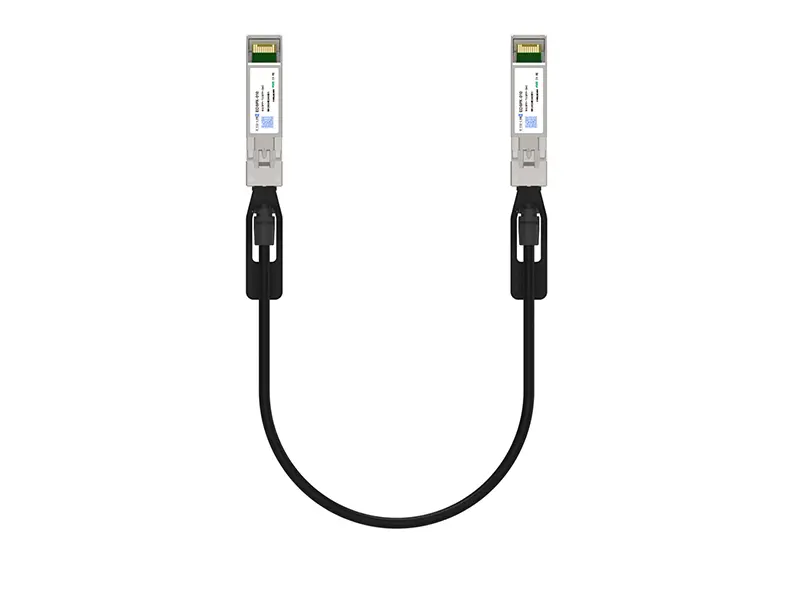 10G SFP+ DAC
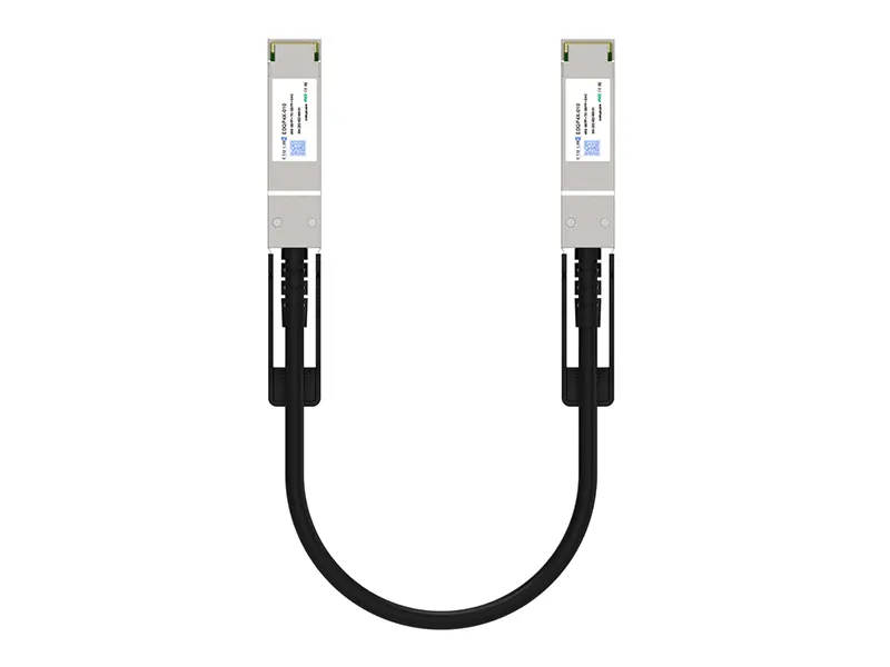 40G QSFP+ DAC
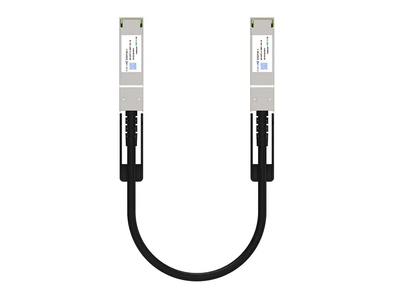 56G QSFP+ DAC
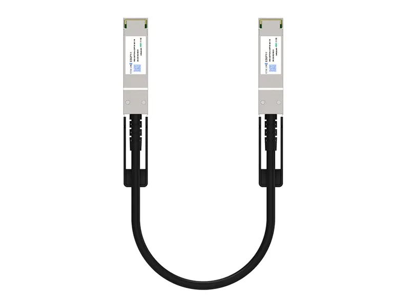 100G QSFP28 DAC
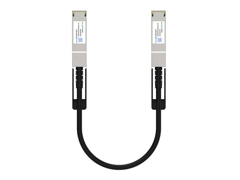 200G QSFP56 DD DAC
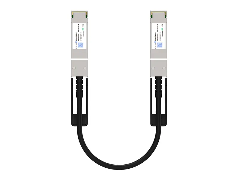 400G QSFP DD DAC
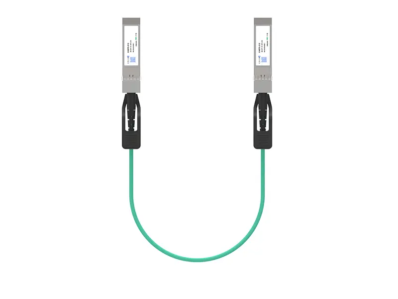 10G SFP+ AOC
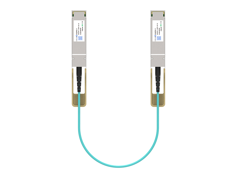 40G QSFP+ AOC
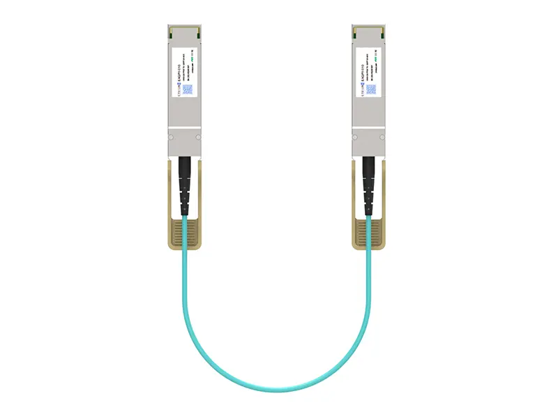 100G QSFP28 AOC
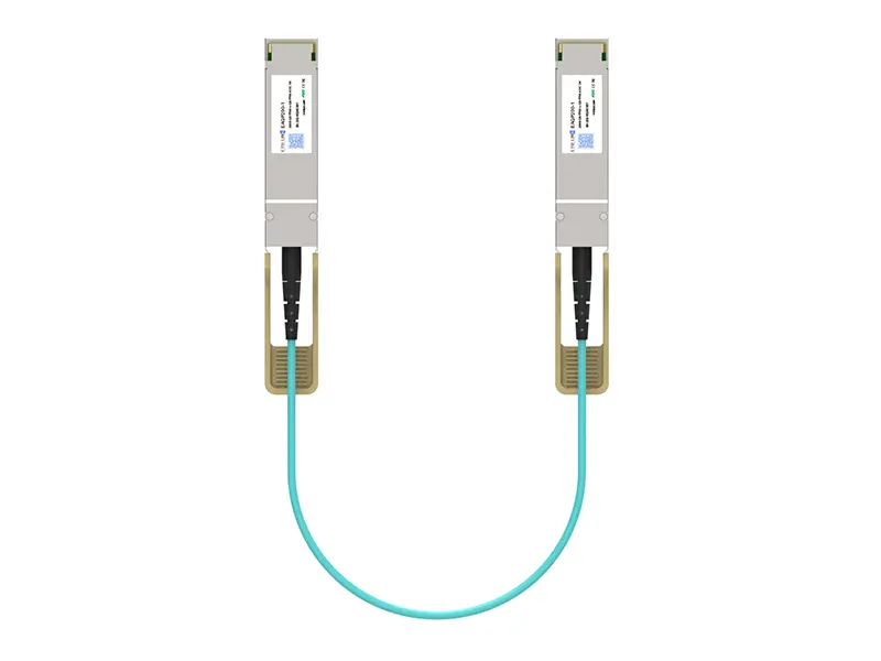 200G QSFP56 AOC
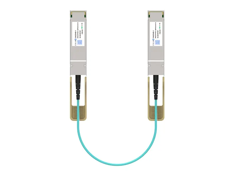 400G QSFP-DD AOC
 Adapter Details
 Media Converter